Bosch Rexroth R911310079 Instrukcja Użytkownika Strona 51
- Strona / 86
- Spis treści
- BOOKMARKI
- Rexroth VSB 40.1 1
- Contents 3
- II Contents VSB 40.1 4
- 7 PC Box 7-1 4
- 9Software 9-1 4
- IV Contents VSB 40.1 6
- 1 System Representation 7
- 1.3 Commissioning 8
- 2.1 Appropriate Use 9
- 2.2 Inappropriate Use 10
- 3.1 Introduction 11
- 3.2 Explanations 11
- 3.3 Hazards by Improper Use 12
- 3.4 General Information 13
- Voltage (PELV) 15
- During Operation and Mounting 17
- 3.11 Battery Safety 19
- 4 Technical Data 21
- 4.3 Power Supply Unit 24 V 22
- 4.4 Ambient Conditions 23
- 4.5 Used Standards 23
- 4.6 Wear Parts 24
- 4.7 Compatibility Check 25
- 4-6 Technical Data VSB 40.1 26
- Foto_Anschluesse_vorne_k.jpg 27
- Foto_Anschluesse_LS_k1.jpg 27
- (outer dimension) 28
- 350 (Distance mounting hole) 29
- 262 (outer dimension) 30
- (distamce 31
- 5.3 Installation Notes 32
- 6.1 Power Button 33
- Fig. 6-2: Graphics Properties 34
- Fig. 6-3: "Devices" 34
- Activation of the VDP or the 34
- Bestätigen.bmp 35
- Fig. 6-5: “Hot Keys“ 36
- 7 PC Box 37
- 7.2 Interfaces 38
- Serial Interface XCOM 39
- Parallel Interface XLPT 40
- XUSB Interfaces 41
- Ethernet Interface XLAN 42
- XVGA Interface 42
- Fig. 7-7: VGA interface 43
- Keyboard Interface XKB 44
- Mouse Interface XMouse 44
- G4 Display Interface X71 45
- PC Power Supply 46
- Sichertrafo.cdr 47
- Wechsel.cdr 47
- 7-12 PC Box VSB 40.1 48
- 230V_Buchse.cdr 49
- 7-14 PC Box VSB 40.1 50
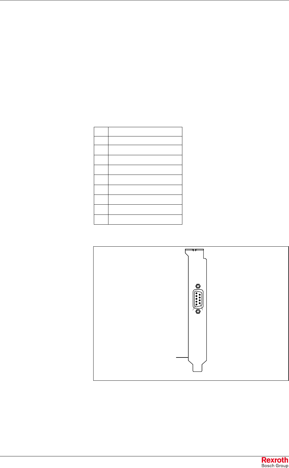
- CFG-VSN01E1-NN-NN-NN-NN-NN-S3 51
- Serial Interface RS232 51
- CFG-VSN01E1-NN-NN-NN-NN-S3-S3 52
- CFG-VSN01E1-NN-NN-NN-NN-NN-S2 53
- 7-18 PC Box VSB 40.1 54
- Jumper Setting on Motherboard 54
- CFG-VSN01E1-NN-NN-NN-NN-NN-S6 55
- 7-20 PC Box VSB 40.1 56
- 8.1 General Information 57
- 8.2 CMOS Battery 57
- Mounting the UPS 58
- 8.4 Hard disk 59
- 83_Gehäuse.JPG 60
- 83_Laufwerk2.JPG 61
- 83_offen.JPG 61
- 83_LS_Gehäuse.JPG 62
- 83_LS_oeffnen.JPG 62
- 83_LS_gekippt.JPG 63
- 83_LS_offen2.JPG 63
- 83_LS_Schrauber.JPG 64
- Fastening screw 65
- 8.5 Extension Cards 66
- 84_Deckeloffen.JPG 67
- 84_Slotblech2.JPG 67
- BIOS Settings 68
- 9 Software 69
- 9-2 Software VSB 40.1 70
- 10.1 Disposal 71
- 10.2 Environmental Protection 71
- Recycling 72
- 11 Ordering Information 73
- 11.2 Accessories 74
- 12 List of Figures 75
- 12-2 List of Figures VSB 40.1 76
- VSB 40.1 List of Figures 12-3 77
- 12-4 List of Figures VSB 40.1 78
- 13 Index 79
- 13-2 Index VSB 40.1 80
- VSB 40.1 Index 13-3 81
- 13-4 Index VSB 40.1 82
- 14 Service and Support 83
- Service and Support VSB 40.1 84
- R911310079 86
© 2020, manymanuals.pl. Wszelkie prawa zastrzeżone. | 0.019 s |
 Manymanuals.com
 Manymanuals.de
 Manymanuals.fr
 Manymanuals.it
 Manymanuals.pl
 Manymanuals.cz
 Manymanuals.es
 Manymanuals-pt.com
Komentarze do niniejszej Instrukcji